![]()
DJI Gimbal FOC
The aim of this project is to be able to use the 3-axis DJI gimbal with a custom open source controller like SimpleFOC. This high quality gimbal is very tiny and easy to find as a replacement part which makes it very suitable for DIY projects.
Pinout identification
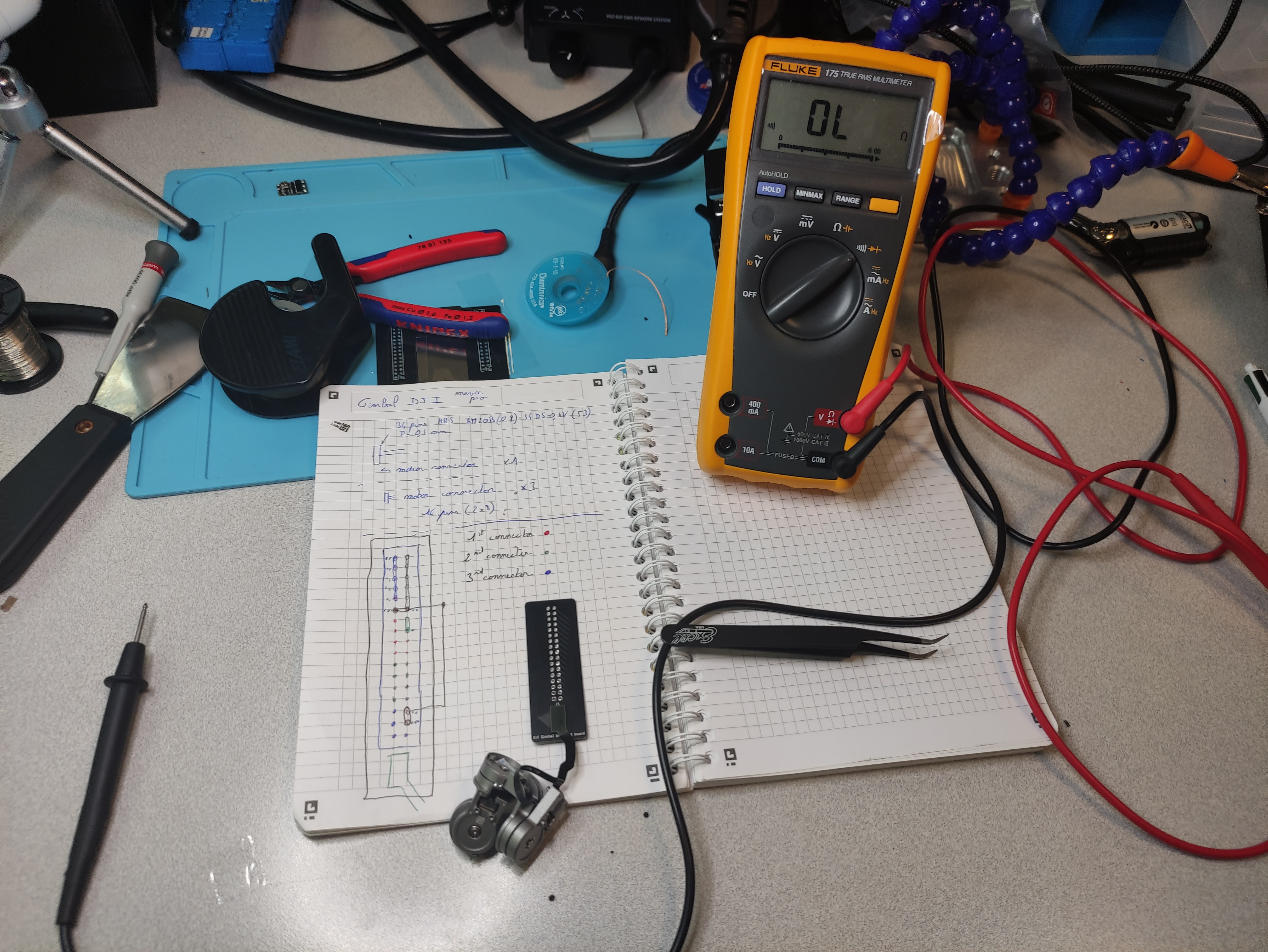
The Gimbal is composed of a flex PCB with a main connector and 3 smaller for each motor. The main end connector is a 40-pin mezzanine board to board connectors. In order to work easily I have designed a breakout board which open to a 2.54" header. (Kicad folder)
Here is the strategy I followed to find the pinout:
-
Find all equipotential pins with a multimeter set to continuity tests, and test all the combinations
-
Group remaining pins by motor with the multimeter find all the pins connected to the motor connector. (Reapeat 3 times for the other connectors)
Open-loop control
Each motor has its own drivers a MP6536. Which makes it easy as no additional hardware is necessary to drive the motors. There are 4 pins from the MP6536:
- PWM1
- PWM2
- PWM3
- Fault : Output. When low, indicates overtemperature, over-current, or under-voltage.
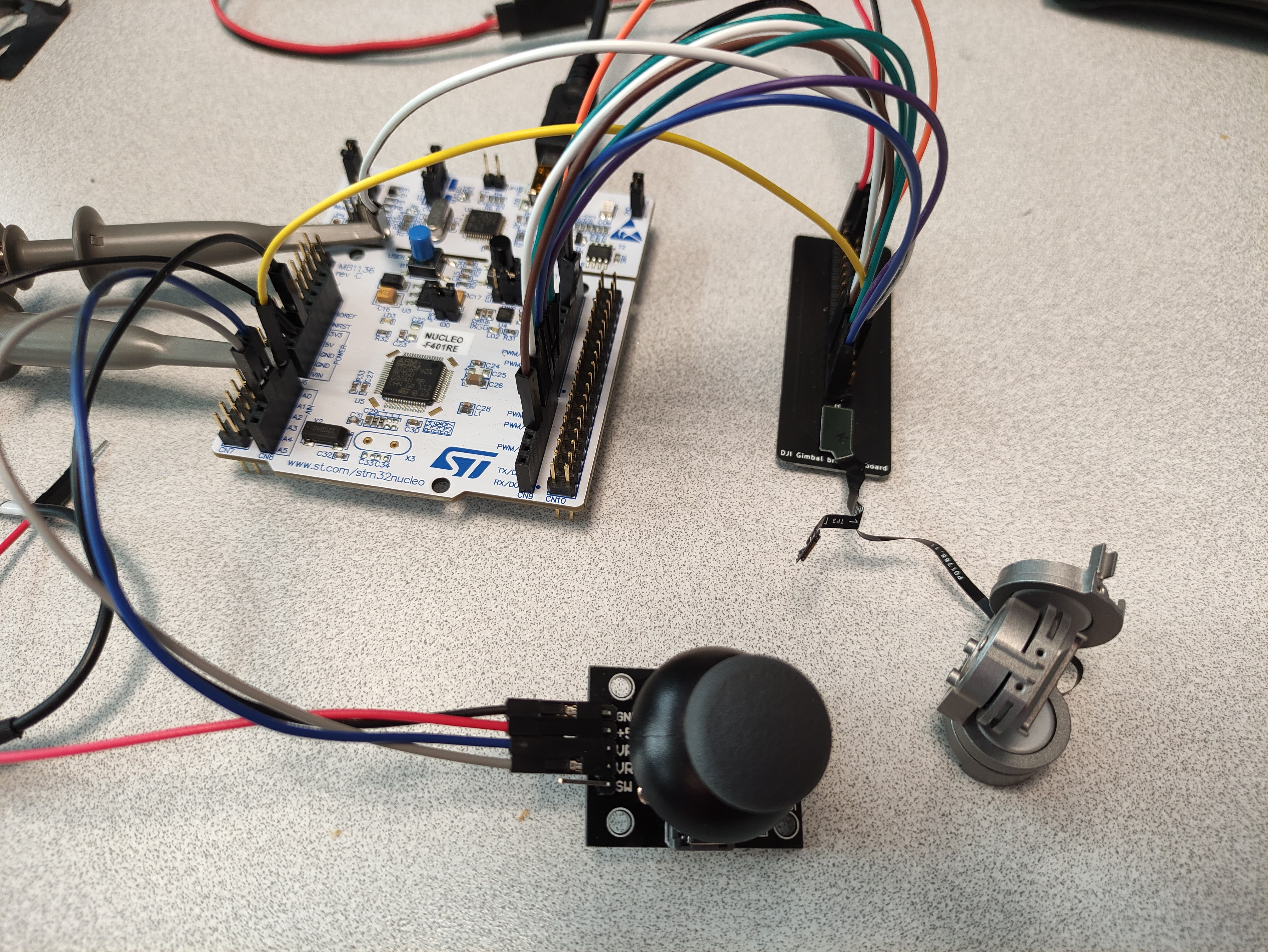
Connected directly to a MCU (here a STM32 Nucleo F401RE) and with the Simple FOC Library, open-loop control works quite well. However due to open-loop control, it cannot know when a "step" is missed so misalignment can occur. Also, the motor tends to become quite hot due to the continuous current sent to the coils.
Position estimation with the integrated linear hall sensors
1. Setup
Each motor is composed of two absolute linear hall sensors. (Texas Instrument DRV5053 Analog-Bipolar Hall Effect Sensor) They are placed at around 120º from each other (eyes measured) and measure the magnetic field of the rotor.
They are linear sensor, the output voltage correspond to a magnetic fields, regardless of the voltage supplied. In our case the output signal is between 1V and 1.65V.
2. Measures
These oscilloscope traces are the sensor output when rotating the rotor forth and back. (a bit less than 180º on the 3rd motor) The channel 0 (Yellow) is the Hall 1 and the Channel 1 (Green) is the Hall 2
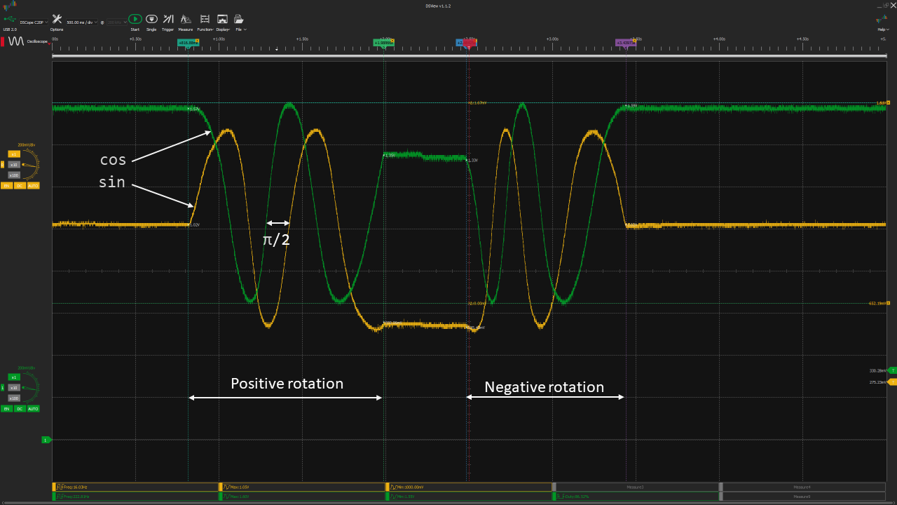
We can see that in the first movement (positive rotation), the green is out of phase of π/2.`
3. Encoding the position
- Get the absolute angle within a period
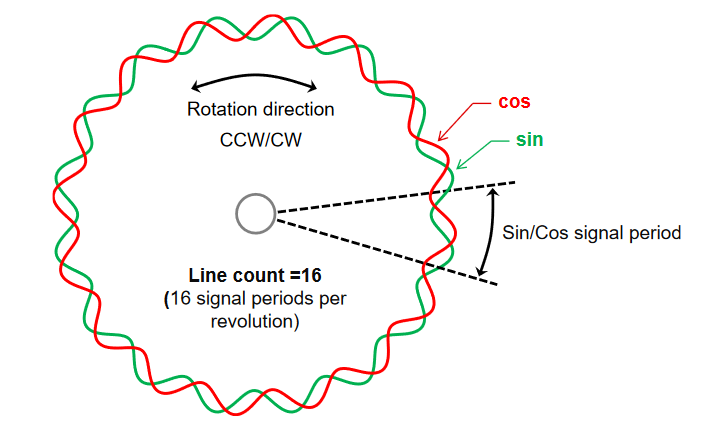
Since the 2 signals correspond to a cos and sin signals, it is possible to compute the angle inside the period using arctan2 function. However, we have more than one period, it is so necessary to increment a position.
\theta= atan2(a,b)
- Incremental position
To increment the position, it is necessary to start from 0 at a known postion. For that the motor is moved in open loop to one end and the position is set to 0. Then we need to sum all the delta of movement at each measure sample.
\phi_t=\phi_{t-1} + (\theta_t - \theta_{t-1})mod(-\pi;\pi)
Coding the solution
- Get the angle in the period
In order to compute the angle from the cos and sin with atan, it is necessary to remap the values of the analog readings from -1 to 1. Beforehand, the maximum and minimum peak of the signals need to be found. It can be done by swiping the motor on startups in open-loop mode. Then the arctan function can be applied. It is preferable to use arctan2 as it will give an angle within the 4 quadrants (-π,π). Whereas arctan give an angle between (-π/2,π/2). Wikipedia
float LinearHallSensor::Callback()  // Return the estimated position of the sensor
{
    A = norm(analogRead(CH1),minCh1, maxCh1);   //read analog values and normalise between [-1;1]
    B = norm(analogRead(CH2),minCh2, maxCh2);

    theta = atan2(A,B); // Compute the absolute angle in the period

    phi = phi + dist_angle(theta, theta_prev);  // increment the difference

    theta_prev = theta; // save for next time

    return phi;
}

float norm(float x, float in_min, float in_max) //return the input value normalised between [-1;1]
{
    return (float)(x + 1.0) * (2.0) / (float)(in_max - in_min) -1.0;
}

float dist_angle(float newAngle, float prevAngle) // return the difference modulo [-pi;pi]
{
    float diff = newAngle - prevAngle;
    while (diff < (-M_PI))
        diff += 2 * M_PI;
    while (diff > M_PI)
        diff -= 2 * M_PI;
    return diff;
}
Tuning the PIDs
To achieve position control it is necessary to have first, a velocity controller well tuned, as they are in cascade. (SimpleFOC implementation and diagram)

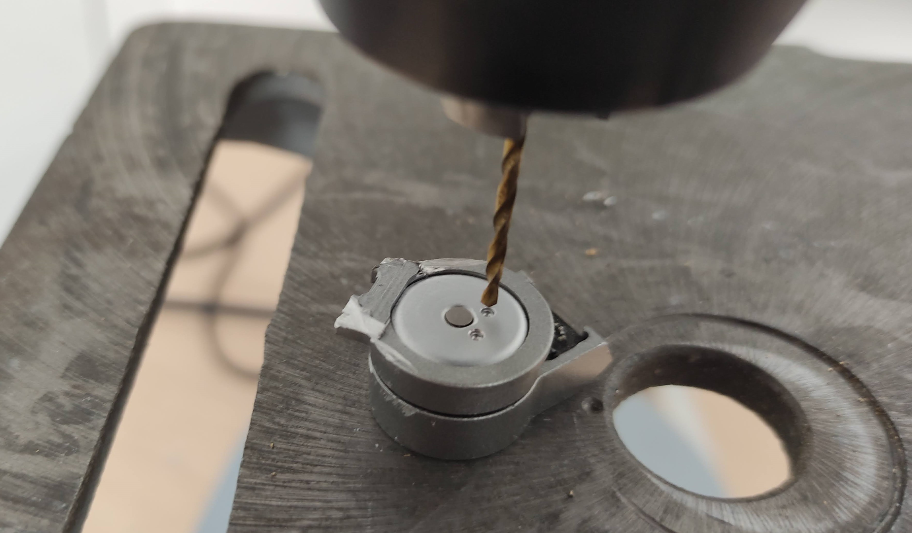
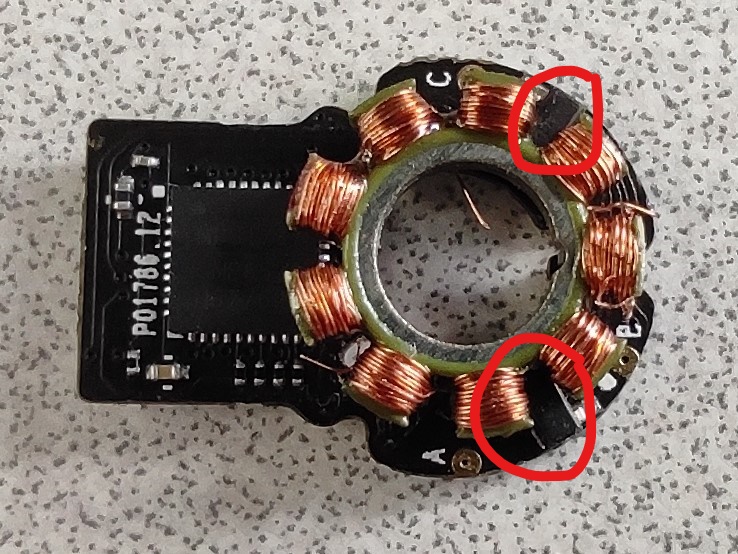
However, the motors of the gimbal have hard stops and can only rotate around a half turn. It was so necessary to remove these mechanical stops. I drilled with a 1.6 mm drill the two little holes to remove it. Then the motor was able to rotate freely and PID can be tuned.